I asked this question also in Electrical Engineering (stack exchange), however on question is more appropriate on this board (question 5). For completeness, I kept all questions intact, but made question 5 bold.
Electrical Engineering StackExchange Question Link: Using a MIDI connector both as MIDI In and Out (not simultaneously),
In my current (Arduino) project I have (currently) 3 MIDI INs and 2 MIDI OUTs. However, it would be nice if I can configure each of the MIDI connectors as IN or OUT by software (Arduino).
The circuits I am using are:
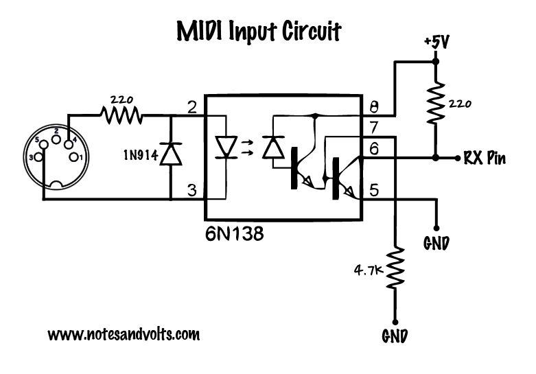
And
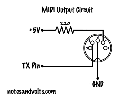
What I would like is to use the connector shown in the above picture as MIDI In OR MIDI out. I have not tried it yet, since I have too many doubts and I do not want to break a component. However, I thought about it (with my limited electronic knowledge), and I think:
Pin 2 afaik for MIDI In, normally has +5V. In the MIDI Input circuit it is not connected, but in the MIDI Output circuit, it is connected to GND. I don't think this is good when being used as MIDI out, resulting in a short circuit (?). So I guess I have to make it +5V when used as MIDI Input and GND when used as MIDI Output (so putting HIGH or LOW 'digital' for Arduino).
Pins 1 and 3 remain in both circuits untouched (so I assume I can do the same).
Pin 4 and 5 is a bit tricky, since they are connected. I think I have to use one or two transistors to create two alternative paths for pins 4 and 5 for MIDI Input and Output. Or can I just set a specific voltage on pins 4 and 5 when used as MIDI In or Out? (and what would those values be?).
For the MIDI input, an optocoupler is used, while for MIDI output, directly the Arduino is used. I wonder if I have to use for both an optocoupler (since people might connect it accidentally to a MIDI output from a MIDI device.
5. I'm not sure how to handle the RX and TX pins ... for 5 MIDI devices, I would need to use 5 RX and TX pins, but the Arduino (Mega) only has 4 of each. But this is probably a question for the Arduino board.