3

I'm making a -12 to +12V DC regulated power supply, on which I want to measure voltage and current with Arduino (through a voltage divider, of course).

I'm not sure, how to either detect nor measure negative voltage. I could "detect" it via a Schottky diode, but I'd get about 0.3V voltage drop, but that's not what I want, because any voltage between 0.0V and -0.3V wouldn't be measured. I want also to be able to measure positive and negative voltage on the same Arduino analog input pin.

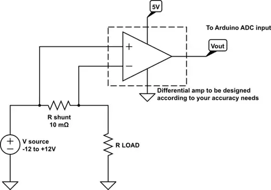
And furthermore, how to measure current, flowing into both ways? (not an AC current, but will change during operation).

I will make additional PCB for this application, so size and number of components isn't important at all.

Enric Blanco
  • 2,124
  • 1
  • 14
  • 25
Jakey
  • 196
  • 1
  • 16

1 Answers1

3

Measuring voltage

Use the following interfacing circuit for measuring voltage:

Voltage translator

Resistors R1, R2, R3 (1% tolerance or better recommended) will map the voltage input range (-12 to +12V DC) to an output range that can be read will the Arduino ADC (+0.5 to +4.5V DC, in order to have some slack from the top and bottom end of the ADC range). The actual theoretical input range would be -15 to 15V DC.

The optional (but recommended) Schottky diodes D1 and D2 will protect the Arduino analog IN pin that you connect to Vout from any input under/overvoltage outside the -15 to +15V DC range.

This is the resulting input to output voltage translation curve:

Voltage translator curve

Measuring current

For measuring current, use a current shunt (i.e., a very low resistance resistor, in the milliohm range) and measure the voltage drop on it via a high input impedance differential amplifier, then sample the output of the amp with the Arduino ADC.

schematic

simulate this circuit – Schematic created using CircuitLab

Follow this link to an article in EE Times to learn more about the main options available for current measurements using a shunt.

Enric Blanco
  • 2,124
  • 1
  • 14
  • 25