5

I am creating a PCB which is a modification of the Arduino on a breadboard. I am intending to buy an USB to Serial breakout from Adafruit so that I can upload my sketches to the atmega 328 I'll be using.

However, in order to reduce power consumption (later I want to run my circuit by using some AA batteries), I would like to turn off the USB to Serial breakout. I thought originally about adding a SPST switch to disconnect it when not using it, but I wonder if it is possible to power it from the USB (whenever I connect something) instead of having to connect its VCC header to the circuit's 5v power.

Is it possible to do that? Or is there any other way I to accomplish this that I'm not thinking of?

UPDATE: For clarity sake, I will explain my design choices: I want this circuit to power some peristaltic pumps that work on 12V. Thus, I'm providing 12V for the pumps and using a regulator to lower the voltage to the circuit. I don't see this is a huge problem for power consumption because the circuit will be in low-power 98% of the time, only waking up one minute per hour. Sometimes, it will run on batteries, which is the reason I wanna eliminate the USB-to-Serial. However, when connected to a power adaptor, I want the USB to be available.

All the best,

Francis

3 Answers3

2

You might be overthinking this. As Gerben points out in the comments, you might want to consider pluging in the USB to Serial breakout board only when required, instead of making it a permanent part of your prototype.

I do this myself in two ways, depending of what I need.

Option 1:

When I foresee a lot of debbuging through the Serial Monitor, I use a permanent pin header so I can attach and dettach the breakout board easily.

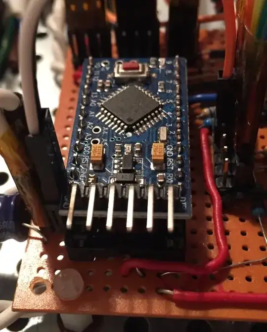
In this case I use a right angle pin header so as to keep a low profile. Like in this Arduino Pro Mini:

90-deg pin header

Option 2:

When I just need to upload the sketch to the Arduino and I know that I won't be using the breakout board from that moment on, I don't solder the pin header in place.

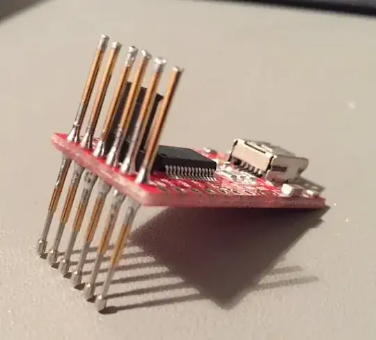
Instead, I've modified another breakout board using pogo pins (spring test probes):

USB to Serial board with pogo pins

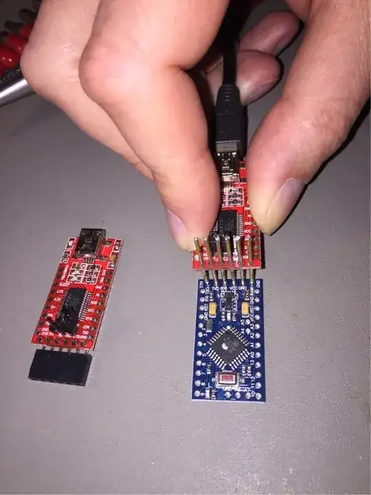
This modified board is what I use to upload the code to the Arduino without any pin header whatsoever. Something like this (I've taken the picture just for illustrative purposes):

Code upload via pogo pins

Enric Blanco
  • 2,124
  • 1
  • 14
  • 25
1

That is not easy to do. You could try diodes and mosfets as switches, but one way or the other, there will probably some leakage current. The 6N137 requires power for the receiving signal.
Other common optocouplers might have leakage current in the nA range for the transistor output. That might be possible. Connect the GNDs. The RX and TX via optocouplers. DTR to RESET with 100nF as usual. Maybe you don't need extra inverters when the transistor outputs are used as emitter followers.

Could you make your project with the ATmega328P without the usb-to-serial module ? The Arduino Pro Mini does not have a usb-to-serial either.
Now that I mention the Arduino Pro Mini: Instead of making an Arduino compatible circuit with a ATmega328P, you could also buy a Arduino Pro Mini 8MHz, and remove the voltage regulator and the power led. Then you have the same thing.

That breadboard Arduino tutorial has +5V connected to AREF. Please don't do that. Keep AREF open, or connect a capacitor of 100nF to it to reduce some noise for analogRead.

In the deepest sleep mode, the ATmega328P can run more than a year on three AA batteries. The timer of the WatchDog can be used to wake up.
The voltage of the three AA batteries is directly connected to the VCC of the ATmega328P, without voltage regulator.

A very good tutorial about power saving is this: Nick Gammon about power saving

Jot
  • 3,276
  • 1
  • 14
  • 21
1

Using separate power supplies at the same time for different parts of your system is a bad, bad idea; you never want two separate power supplies potentially pushing current at each other. Using separate +5V power sources for different chips but sharing a common ground across the device and connecting just data lines is problematic, too; as far as I know it's not trivial to do safely. Unless you really know what you're doing, full isolation between separately powered components is the way to go.

The two parts of the system we're talking about here, the USB-Serial converter and the rest of the system, exchange digital data only, and that at only three points, all of which are unidirectional: serial TX, serial RX and DTR. (DTR, when pulled low by the PC, resets the Arduino). Therefore if we can isolate these links not to exchange current when they communicate, we can separately power the devices on each side of this isolation barrier.

This is actually a common problem in things like power supplies (where we want data from the high-voltage side sent to the low-voltage side but don't want the risk that someone touching the low-voltage side could get electrocuted) and motor control boards (where the motors often use a separate power supply from the controller logic to reduce noise passed into the controller logic). One common solution is to use opto-isolators (also called optocouplers). Typically these use an LED and a sensor looking at it from across a gap; when the LED is lit up by one side, the other side sees it and generates a current.

The 6N137 (as used in this answer) or similar chip should work for this: 10 MHz is plenty of bandwith to run a 115,200 baud serial link. Each opto-coupler would be powered by the receiving side (Arduino for its RX and DTR, USB-serial for Arduino's TX) and on the other side you'd connect data to the VF+ pin and ground to the VF- pin. As per note 1 on page 4, you'll need caps at the power supply inputs, and you'll have to add inverters as well if you use this particular opto-isolator, since it inverts the signal; a 74HC04 will give you six of those. If you want to save a dollar, you could not bother to connect the DTR line and just reset the Arduino manually when you want to upload a program, if that's not too inconvenient.

Consumer warning here: I've not actually built this circuit (though I'd like to give it a try one day), so there could be something I'm missing here. (Hopefully someone more expert than me will speak up if that's the case.)

If you're going to be spending any significant amount of time connected to USB power and your whole system can run on less than 500 mA (the limit of the USB supply from many PCs), you may want to consider powering the entire system from USB while it's connected. This can be done in a way similar to how the Arduino Uno board disconnects USB power when receiving power on Vin: switch it with a comparator and a MOSFET.
cjs
  • 594
  • 2
  • 16