8

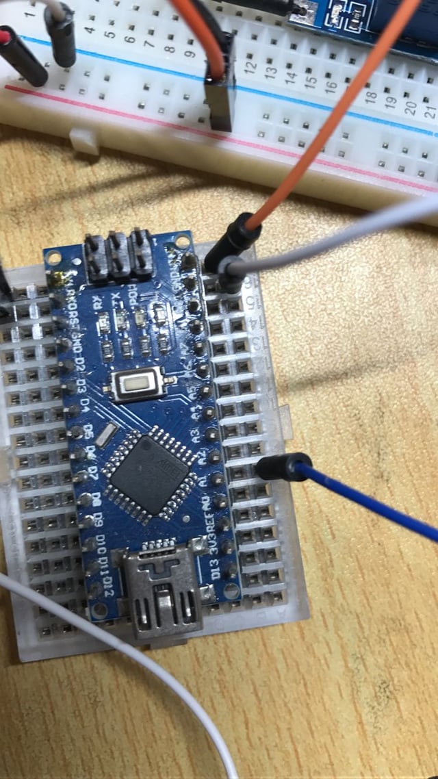
I have a sensor and it generates an analogue signal.

I am reading all analogue data and sending it to my computer.

enter image description here

uint8_t sensors[] = { A0,A1,A2,A3,A4,A5,A6 };
const int len = sizeof(sensors) / sizeof(sensors[0]);
void loop(void)
{
    for (size_t i = 0; i < len; i++)
    {
        auto sensor = sensors[i];
        int sensorValue = analogRead(sensor);
        // Convert the analogue reading (which goes from 0 - 1023) to a voltage (0 - 5V):
        float voltage = sensorValue * (5.0 / 1023.0);
        char t[100];
        sprintf(t, "%d:%d$\n", sensor, sensorValue);
        uint8_t t1[100];
        //PrintSerial.println(t);
        memcpy(t1, t, 100);
        wifi.send(t1, strlen(t));
    }
    delay(300);
}

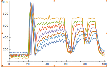
I plotted the analogue reading. Why does the graph look like this?

enter image description here

Enric Blanco
  • 2,124
  • 1
  • 14
  • 25
erow
  • 215
  • 3
  • 5

2 Answers2

11

This is to be expected.

The other pins have nothing connected to it, so their voltage is floating.

The Arduino MCU only has a single ADC. To read the different analog pins, it uses a multiplexer to connect the pin you want to read to the single ADC. The ADC inside the MCU have a "sample and hold" capacitor inside it.

To read the voltage at the pin, it will connect the pin, to charge the sample and hold capacitor. It will then disconnect and measure the voltage of the sample and hold capacitor, one bit at a time.

So in your case, by reading the voltage at the connected pin, it will charge the capacitor. It will then read the unconnected pins. But because nothing is connected the sample and hold capacitor will stay at about the same voltage, because the unconnected pin will neither charge, nor discharge it.

Measuring the voltage on the sample and hold capacitor will slightly lower this voltage, so that's why in the graph the lines will be lower than the previous measurement.

PS Also, because all the pins are placed in a breadboard, you'll have some capacitive coupling between the adjacent pins.

Gerben
  • 11,332
  • 3
  • 22
  • 34
0

The acc is really a little capacitor. As you switch channels, the charges in the acc capacitor get carried from one input channel to the next. If the next input channel is of very high impedance, or very low capacitance, the charges on the acc capacitor dominate and its voltage changes little.

In addition, poor code can cause it too - usually from a lack of sufficient time for the add to complete.

dannyf
  • 2,813
  • 11
  • 13