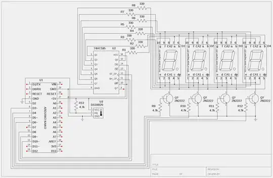
I am working on an Arduino based temperature reader using a DS18B20 temperature IC. The display is a 4 digit 7 segment LED common anode display driven by a single 74HC595 shift register. Currently, it is setup to read a variable assigned with a number to test the display portion. It displays to the tenths decimal place I am having troubles trying to get rid of the leading zeros. When the variable 'tempF' is assigned a number such as 12.3, the display yields 012.3 and if the variable is assigned a number such as 1.2, the display will yield 001.2. At the same time, I was wanting to have it place a minus (-) sign when the number is less than zero. So far, the examples I'm finding on the web don't seem to match into the code I'm currently working with or don't work at all. I haven't been able to locate a sketch that seems to work for this type of setup. I have posted below, the code I am working with. The original code was obtained from the link provided in the sketch.
The sketch there does not provide the means of reading negative temps or suppress leading zeros.
   /*
 * www.pial.net/arduino-controlling-a-4-digit-seven-segment-display/
 */

//#include <OneWire.h>
//#include <DallasTemperature.h>

//#define ONE_WIRE_BUS 2

//OneWire oneWire(ONE_WIRE_BUS);
//DallasTemperature sensors(&oneWire);
//DeviceAddress insideThermometer;

const int ledPin =  13;// LED connected to digital pin 13
const int latchPin = 8;//Pin connected to ST_CP of 74HC595
const int clockPin = 9;//Pin connected to SH_CP of 74HC595
const int dataPin = 10;//Pin connected to DS of 74HC595

const int digitPins[4] = {
  3,4,5,6}; //pins to control the 4 common anode pins of the display

const byte digit[10] = //seven segment digit bits
{
  B00111111, //0
  B00000110, //1
  B01011011, //2
  B01001111, //3
  B01100110, //4
  B01101101, //5
  B01111101, //6
  B00000111, //7
  B01111111, //8
  B01101111, //9
//  B00000000, //all segments off
//  B01000000 //-
};

int digitBuffer[4] = {
  1};
int digitScan = 0;
int soft_scaler = 0;
float tempC, tempF;
int tmp;

void setup()   {
  TCCR2A = 0;
  TCCR2B = (1<<CS21);
  TIMSK2 = (1<<TOIE2);
  TCNT2 = 0;
  Serial.begin(9600);

  pinMode(ledPin, OUTPUT);
  for(int i=0;i<4;i++)
  {
    pinMode(digitPins[i],OUTPUT);
  }
  pinMode(latchPin, OUTPUT);
  pinMode(clockPin, OUTPUT);
  pinMode(dataPin, OUTPUT);

//  sensors.begin();
//  sensors.getAddress(insideThermometer, 0);
}

ISR(TIMER2_OVF_vect) {
  soft_scaler++;
  if(soft_scaler==15)
  {
    refreshDisplay();
    soft_scaler = 0;
  }
};

void refreshDisplay()
{
  for(byte k=0;k<4;k++)
  {
    digitalWrite(digitPins[k], LOW);
  }
  digitalWrite(latchPin, LOW);
  shiftOut(dataPin, clockPin, MSBFIRST, B11111111);
  digitalWrite(latchPin, HIGH);
  delayMicroseconds(50);
  digitalWrite(digitPins[digitScan], HIGH);

  digitalWrite(latchPin, LOW);
//  if (digitScan==3)
//  {
//    shiftOut(dataPin, clockPin, MSBFIRST, ~(digit[digitBuffer[digitScan]] | B00000000)); //inserting the blank
//    }
//    else
//  {
//    shiftOut(dataPin, clockPin, MSBFIRST, digit[digitBuffer[digitScan]]);
//  }

  if(digitScan==1)
  {
    shiftOut(dataPin, clockPin, MSBFIRST, ~(digit[digitBuffer[digitScan]] | B10000000)); //inserting the dot
  }
  else
  {
    shiftOut(dataPin, clockPin, MSBFIRST, ~digit[digitBuffer[digitScan]]);
  }
  digitalWrite(latchPin, HIGH);
  digitScan++;
  if(digitScan>3) digitScan=0;
}

void loop()
{
  digitalWrite(ledPin, HIGH);
  boolean sign = false;
  //sensors.requestTemperatures();
  //tempC = sensors.getTempC(insideThermometer);
  //tempF = DallasTemperature::toFahrenheit(tempC);
  //tmp = int(tempF*100);
  tempF = 0.2;
  tmp = int(tempF*10);

//   if (digitScan == 4 ){
//    shiftOut(dataPin, clockPin, MSBFIRST, ~(digit[digitScan] | B00000000)); //inserting the blank
//    }
//    else
//  {
//    shiftOut(dataPin, clockPin, MSBFIRST, digit[digitBuffer[digitScan]]);
//  }

//if (tmp < 0){
//sign = true;
//tmp = abs(tmp);
//}

//if (digitScan == 3) {
//  if (tmp < 0){
//    shiftOut(dataPin, clockPin, MSBFIRST, ~(digit[digitBuffer[digitScan]] | B01000000)); // outputs minus sign
//  }
//  else {
//    shiftOut(dataPin, clockPin, MSBFIRST, ~(digit[digitBuffer[digitScan]] | B00000000));
//   }

//  tmp = abs(tmp);
// }
//  else if (digitScan == 3 && digit[digitScan-1] == 0) { // writing on the second display (tens; if there are none, outputs nothing)
//     shiftOut(dataPin, clockPin, MSBFIRST, ~(digit[digitBuffer[digitScan]] | B00000000));
//   }
//   else if (i == 2) { // writing on the third display, where decimal point is needed
//     shiftOut(data_pin, clk_pin, MSBFIRST, digit[digitBuffer[i-1]]);
//   }
//   else { // writing on "other" displays (in fact fourth display AND seecond display only if there are some tens)
//     shiftOut(data_pin, clk_pin, MSBFIRST, digit[digitBuffer[i-1]]);
//   }


  digitBuffer[3] = int(tmp)/1000;
  digitBuffer[2] = (int(tmp)%1000)/100;
  digitBuffer[1] = (int(tmp)%100)/10;
  digitBuffer[0] = (int(tmp)%100)%10;
  Serial.print("number assigned to the variable 'tmp' = ");
  Serial.println(tmp);
  Serial.print("number assigned to the variable 'tempF' = ");
  Serial.println(tempF);
  digitalWrite(ledPin, LOW);
  delay(500);
}
The commented out commands in the sketch were attempts to remove leading zeros and add a minus sign when needed but failed. I have also posted a schematic of the project as well. A 74HC595 was used in this manner to free up pins to be used later in a deep freezer project.
I am by no means an expert programmer but if anyone could help me out or provide some insight on how to solve this problem, it would be most appreciated.


