First of all I'm a noob.
I was trying to do the H-Bridge using 2N2222 controlled by an Arduino Uno.
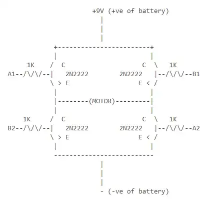
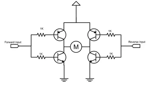
This is the design--->
I joined A1 and A2 to form a common terminal (say A), similarly, I joined B1 and B2 to form B. Now I connected A and B to 2 pins of the arduino (say pin 9 & pin 10 respectively).
So, theoretically, when I should digitalWrite pin 9 HIGH, then current should flow via A1 and A2, i.e. left to right in the motor AND when I should digitalWrite pin 10 HIGH, then current should flow via B1 and B2, i.e. right to left in the motor.
Hence, I can control the direction of rotation of the motor.
BUT.....it wasn't working...!!!!
I need help...!!!
After much thinking I had a hunch...."Perhaps, I am not giving GROUND to the transistors". I thought about it, but was unable to figure out the way of doing it.
So, again, please help me...!!!

