13

Regarding my program, it is a program that does some calculations and then outputs a voltage based on the result using analogWrite function. However my problem is that I had done my programming based on a misconception that analogWrite function via PWM does output an analog voltage, where in fact it only "simulates" the analog voltage instead.

Here are the relevant parts of my code :

int pwmOutput = 11;
int pwm = 0;

void compareNewOldVoltageYes(void)
{
  if(pv_Vnew > pv_Vold && pwm != 255)
  {
    ++pwm;           //increasing value
  }
  else if(pwm != 0)
  {
    --pwm;           //decreasing
  }
}

void compareNewOldVoltageNo(void)
{
  if(pv_Vnew > pv_Vold && pwm != 0)
  {
    --pwm;
  }
  else if(pwm != 255)
  {
    ++pwm;
  }
}

void loop() 
{
   reading();
   PowerCalculation();

   if(pv_NewP > pv_OldP)
   {
      compareNewOldVoltageYes();
   }
   else
   {
      compareNewOldVoltageNo();
   }

   analogWrite(pwmOutput, pwm);           //analogWrite

   float displayPWMvolt = pwm * 0.0196;

   Serial.print("Output Voltage: ");
   Serial.print(displayPWMvolt);
   Serial.println(" V");

   pv_OldP = pv_NewP;

   Serial.print("Previous Power: ");
   Serial.print(pv_OldP);
   Serial.println(" W");

}

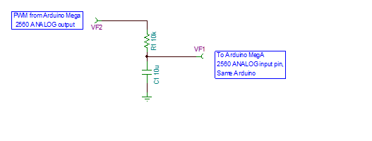
As for the circuitry, output pin 11 is being connected to a 1 ohm resistor and then to GND. (Where I measured the voltage) I am using Arduino Uno board.

UPDATE:

As said in the comments by @DatHa, pwm does not output voltage. Is there a way to output voltage as said, without changing the board?

bytk
  • 133
  • 1
  • 1
  • 9

6 Answers6

13

You basically have three options:

  1. Switch to an Arduino Due which has a built-in DAC which outputs a real voltage.
  2. Add an external DAC chip (such as the MCP4821/2) to create the voltage for you
  3. Use a low-pass filter (R-C network) on a PWM pin.

Of the three options I usually use an MCP4822 since it gives the best results and doesn't cost as much as using a Due.

Majenko
  • 105,851
  • 5
  • 82
  • 139
7

At 5V, a 1 ohm resistor will try to sink 1A and far exceed the 40mA specs. Please use at least a 5/0.040=125 ohm resistor to protect your pin. And if you put the a capacitor between your resistor and ground, the RC circuit of the capacitor will smooth out the PWM into an analog voltage.

Please try the suggested @russell answer with a 47K resistor and 1uF capacitor, you will get an analog voltage at the junction to use with your electronic load.

Dave X
  • 2,350
  • 15
  • 29
2

As far as I know Arduinos have ADC (Analog to Digital Converters) but do not have any DAC (Digital to Analog Converters). So you can not output a set voltage from any pins based on a digital value.

Andre Courchesne
  • 676
  • 5
  • 11
1

There is no direct way.

In addition to @Majenko

Alternative way: you can use H bridge like L293d to provide continuous level. Many diy inverter circuits are useing this technique.

http://www.instructables.com/id/How-to-Make-an-Inverter-Using-ARDUINO/?ALLSTEPS

acs
  • 235
  • 5
  • 16
0

NO.. There is no way to get an analog voltage from the Arduino. The best that you can do is to use Arduino as a Buck Voltage converter in linear or boost mode using a voltage regulator, inductor and the mosfet transistor. You will also might need to use a Mega or Dulorme which provide a PWM frequency other that the standard 50o Hz.

Best luck

0

I wondered if this would give a more stable output.

PWN presented to RC.  Cap charges, sample is made by another analog input.  When PWN pin goes low, slow discharge of cap.  Maybe a large resistor is needed in parallel with the cap for slow discharge?