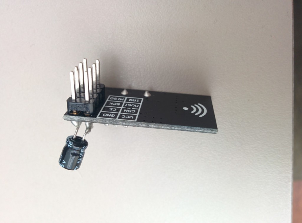
I am trying to connect my Arduino Pro Mini 3.3V to an nRF24L01 transceiver and cannot see what I am doing wrong. I've checked my wiring a million times because the problem hints there is an invalid or no connection between the Arduino and the transceiver. I have the following pin connections:
Arduino --------------- nRF24L01
--GND ------------------- GND
--VCC ------------------- VCC
---D9 --------------------- CE
--D10 -------------------- CSN
--D13 -------------------- SCK
--D11 -------------------- MOSI
--D12 -------------------- MISO
I am using the following sketch
#include <SPI.h>
#include "nRF24L01.h"
#include "RF24.h"
#include "printf.h"

RF24 radio(9, 10);

const uint64_t pipes[2] = { 0xF0F0F0F0E1LL, 0xF0F0F0F0C2LL };     //Addresses to send/receive

void setup()
{
  printf_begin();
  Serial.begin(9600);
  radio.begin();
  radio.setRetries(15, 15);
  radio.openReadingPipe(1, pipes[0]);
  radio.printDetails();
  radio.stopListening();
}

void loop()
{
  const char text[] = "Hello World";
  radio.write(&text, sizeof(text));

  delay(1000);
}
I have no clue where I am going wrong. This setup works well on my Uno, however I cannot replicate it on the Arduino Pro Mini. Can anyone tell me if I am doing something super wrong that would prevent this from working? I'm all out of ideas. Appreciate any help in advanced!
Update:
I forgot to copy and paste the output from printDetails():
STATUS  = 0x00
RX_DR=0
TX_DS=0
MAX_RT=0
RX_P_NO=0
TX_FULL=0
RX_ADDR_P0-1    = 0x0000000000 0x0000000000
RX_ADDR_P2-5    = 0x00 0x00 0x00 0x00
TX_ADDR = 0x0000000000
RX_PW_P0-6  = 0x00 0x00 0x00 0x00 0x00 0x00
EN_AA   = 0x00
EN_RXADDR   = 0x00
RF_CH   = 0x00
RF_SETUP    = 0x00
CONFIG  = 0x00
DYNPD/FEATURE   = 0x00 0x00
Data Rate   = 1MBPS
Model   = nRF24L01
CRC Length  = Disabled
PA Power = PA_MIN