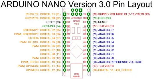
Regarding “The data pins will be wired to pins 6, 8, 9, 12 and 13 and each will have a 470 ohm 1/2W resistor on each pin”, note that WS2812s typically are connected together in strings, with the DO (data out) pin of each upstream unit connected to the DI (data in) pin of the next unit downstream. Thus, there is no need to allocate five Arduino IO pins; one is enough.
For further background on WS2812 mechanisms, see for example Is it possible to infer the length of a neopixel string using 1-wire protocol?, and see discussions and diagrams at adafruit.com and sparkfun.com.
Regarding use of an efficient step-down switching-supply voltage regulator set for 12 V out, if you use an adjustable regulator you might as well set it lower than that, for example at 8 or 9 volts. Typically, the regulators on Arduino boards that convert Vin to +5 or +3.3 V are linear regulators rather than switching regulators, so every unnecessary extra volt (above the dropout limit) proportionally increases the amount of wasted energy.
In typical use, a WS2812 draws 20 to 60 mA current, supposing up-to-five-volt power. Thus, a string of 30 to 40 of them will draw at least 0.6 A, in most cases, and up to 2.4 A, if all are on at top brightness. In either case, an external power supply would be de rigueur. You would connect the external supply's ground to the Nano's ground; the +5Vs need not be connected together.
Edit: Addressing questions from comments
Re “if one data in will control the entire array of LEDs, it should be connected to D13”, I'm not aware of any reason for that idea, and indeed would recommend against it. On many Arduino models, D13 drives an LED. While the Uno uses a buffer amplifier to drive the LED, the Nano just has a 680 Ω resistor in series with an LED. I'd not load it further.
Wiring each of several strips in its own chain seems quite reasonable. Yes, you could wire all the DIs of 30 or 40 WS2812 units in parallel. However, parallel inputs would require 30 or 40 wire runs, vs. the simple wiring chain the WS2812 is intended for. Note, per its spec sheet the WS2812 DI load is ±1 µA max, so one '328 IO pin could drive hundreds of them. But input capacitance, up to 15 pF each, probably precludes driving thousands in parallel.
If performance is an issue, possibly use short chains (up to several dozen units long) in parallel, rather than one long chain of hundreds of units. The spec sheet says, “When the refresh rate is 30fps, low speed model cascade number are not less than 512 points, high speed mode not less than 1024 points.” (Low speed refers to 400Kbps signalling; high speed, 800Kbps).
Note, paralleled chains improve refresh rates only when multiple chains are used to show the same pattern. Otherwise, each chain being refreshed separately is no faster than refreshing the same number of units in series. The library that drives a chain of WS2812s hogs the whole processor each time it sends a chain of data. Also note that scan rates of 400 Hz are mentioned in the spec sheet. It is likely to be futile to try to exceed that by paralleling units.
Summary: If you have a dozen or so units on a rotor arm, I'd wire them in series. If it's more convenient to keep each arm's wiring separate from that of other arms, then do so. If each arm will show the same pattern as other arms, you could wire the chain inputs (the first units in each chain) in parallel, else would use separate driver pins.
