2

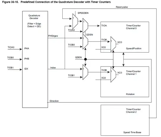
I am working on an autonomous robot in my summer vacations. I am currently working on running the motors of my robot in a closed loop. In order to do so, I have to interface two Quadrature encoders of the motors with the Arduino Due that I have. My motor encoder have 3200 Edges per Revolution. I have read the Atmel SAM3x8E datasheet and have successfully tested one encoder in Arduino IDE. It appears that TIOA0 and TIOBO are used to read PHA and PHB of of one Encoder which correspond to Pin 2 and 13 of Arduino Due. I am not using Index pin (TIOB1).

enter image description here

It seems that I can only interface 1 quadrature .Is their any way I can use Quadrature decoder to read 2 encoders instead of one. As I have stated earlier I am not using the index pin. So, maybe there might be a way to decode to encoders using the three available pins as shown in the above diagram. I don't want to use Interrupts to do this job.

Here's is the link of SAM3x Manual: http://www.atmel.com/Images/Atmel-11057-32-bit-Cortex-M3-Microcontroller-SAM3X-SAM3A_Datasheet.pdf

Link of Motor that i am using: www.pololu.com/product/2824
Masood Salik
  • 47
  • 2
  • 9

1 Answers1

1

According to Quadrature Decoder QDEC for SAM3/4 Devices_ApplicationNote_AT11483 and referenced excel sheet with Device to No of QDEC channels it seems to have two of them. However in DUE almost none of interesting devices are wired to headers completely (Extmem, SD interface,...)

However TIOA6 and TIOB6 should be on pins 5 and 4

Pin configuration should be something like this:

  PIO_Configure(PIOC, PIO_PERIPH_B, PIO_PC25B_TIOA6, PIO_DEFAULT);
  PIO_Configure(PIOC, PIO_PERIPH_B, PIO_PC26B_TIOB6, PIO_DEFAULT);

And TC0 is pretty much same as TC2, so just copy&paste and change TC0 to TC2

Full config:

  REG_PMC_PCER0 = PMC_PCER0_PID27 | PMC_PCER0_PID28 | PMC_PCER0_PID29; 
  REG_PMC_PCER1 = PMC_PCER1_PID33 | PMC_PCER1_PID34 | PMC_PCER1_PID35;

PIO_Configure(PIOB, PIO_PERIPH_B, PIO_PB25B_TIOA0, PIO_DEFAULT); // arduino pin 2 PIO_Configure(PIOB, PIO_PERIPH_B, PIO_PB27B_TIOB0, PIO_DEFAULT); // arduino pin 13

REG_TC0_CMR2 = TC_CMR_TCCLKS_TIMER_CLOCK4 | TC_CMR_WAVE | TC_CMR_ACPC_TOGGLE | TC_CMR_WAVSEL_UP_RC; REG_TC0_RC2 = F_CPU / 128 / 1; REG_TC0_CMR0 = TC_CMR_ABETRG | TC_CMR_LDRA_EDGE | TC_CMR_LDRB_EDGE | TC_CMR_ETRGEDG_EDGE | TC_CMR_CPCTRG; REG_TC0_BMR = TC_BMR_QDEN | TC_BMR_SPEEDEN /| TC_BMR_EDGPHA/; REG_TC0_CCR0 = TC_CCR_CLKEN | TC_CCR_SWTRG; REG_TC0_CCR1 = TC_CCR_CLKEN | TC_CCR_SWTRG; REG_TC0_CCR2 = TC_CCR_CLKEN | TC_CCR_SWTRG;

PIO_Configure(PIOC, PIO_PERIPH_B, PIO_PC25B_TIOA6, PIO_DEFAULT); // arduino pin 5 PIO_Configure(PIOC, PIO_PERIPH_B, PIO_PC26B_TIOB6, PIO_DEFAULT); // arduino pin 4

REG_TC2_CMR2 = TC_CMR_TCCLKS_TIMER_CLOCK4 | TC_CMR_WAVE | TC_CMR_ACPC_TOGGLE | TC_CMR_WAVSEL_UP_RC; REG_TC2_RC2 = F_CPU / 128 / 10; REG_TC2_CMR0 = TC_CMR_ABETRG | TC_CMR_LDRA_EDGE | TC_CMR_LDRB_EDGE | TC_CMR_ETRGEDG_EDGE | TC_CMR_CPCTRG; REG_TC2_BMR = TC_BMR_QDEN | TC_BMR_POSEN /| TC_BMR_EDGPHA/; REG_TC2_CCR0 = TC_CCR_CLKEN | TC_CCR_SWTRG; REG_TC2_CCR1 = TC_CCR_CLKEN | TC_CCR_SWTRG; REG_TC2_CCR2 = TC_CCR_CLKEN | TC_CCR_SWTRG;

KIIV
  • 4,907
  • 1
  • 14
  • 21