5

So I'm looking to create an arduino clone to mount on one of my robots. I started off making the arduino on a breadboard, using the instructions found on Arduino's own website and I succeeded. It works as well, I've checked it with the "blink" project.

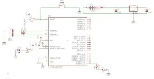
I then drew the schematic in Eagle: schematic

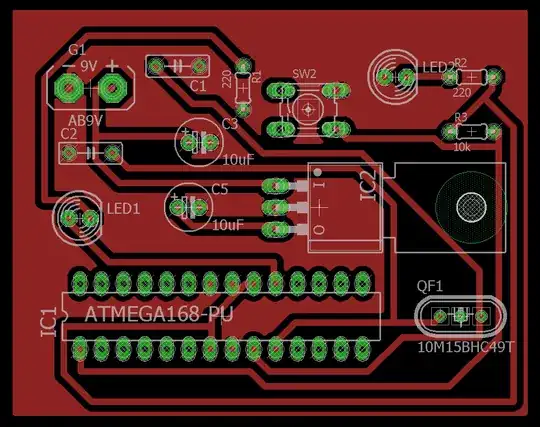
Next, I created a board and routed it, giving the following result:

Finally, I transferred it onto a copper clad, soldered it, but it doesn't work. Tried pretty much everything I could think of but there seems to be something wrong and I cant work out what it is.

Can someone please help?

Hassan

RSM
  • 1,457
  • 1
  • 11
  • 26
Hassan M
  • 171
  • 5

1 Answers1

8

I haven't worked out why it's "not working", but some comments on your PCB:

  1. Your crystal is too far from the clock pins
  2. Your crystal capacitors are most definitely too far from the crystal
  3. There are no decoupling capacitors on your Vcc / AVcc pins

Your crystal should be right next to the pins on the chip that it is connected to, and the capacitors for it should be immediately next to that. The layout you have at the moment, if it actually works, will be radiating huge amounts of EMI and would immediately fail any emissions test you'd care to perform.

Without decoupling capacitors on the power pins the chip may not function properly.

Edit: I have just found your main mistake

You haven't linked the output of your regulator sub-circuit to Vcc. Power gets regulated but goes nowhere.

enter image description here

Majenko
  • 105,851
  • 5
  • 82
  • 139