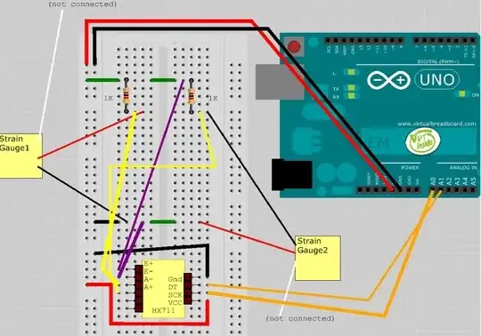
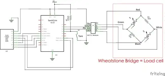
I have two, three-wire load sensors (https://cdn.sparkfun.com//assets/parts/4/5/9/5/10245-01.jpg) hooked up in a half wheatstone bridge (I think), with two 1K resistors. Using a multimeter, I am reading small voltage changes when applying pressure to either strain gauge, when measured on between the pins A+ and A- on the HX711 ADC amp, however my Arduino serial output shows all 0's when using a variety of code examples (for example, this one: http://www.dfrobot.com/wiki/index.php/Weight_Sensor_Module_V1#Sample_code).
My concern is that my circuit is not setup correctly as I am fairly novice, however everything I have researched about wheatstone bridges, and half wheatstone bridges seems fairly straightforward, and seems to match my circuit. Any guidance/advice on the attached breadboard circuit diagram would be extremely helpful.

