-2

I have hacked this kettle so that I can turn it on and off remotely via wifi and that is working perfectly.

enter image description here

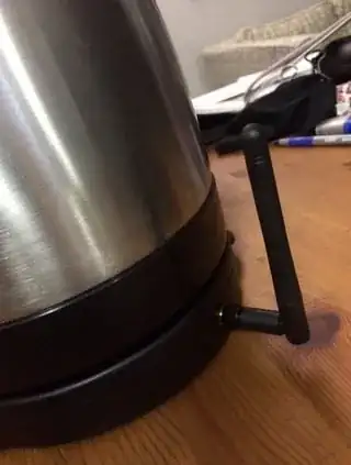
Added this to get a better signal.

enter image description here

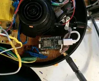
This is my micro controlling the 5v buttons on the kettle.

enter image description here

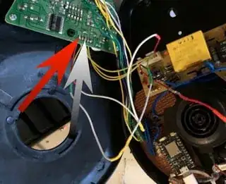
I keep running into a wall when it comes to reading the temperature of the water. The kettle does this automatically, but I want to transfer this information to my micro.

If I hook my multimeter to the ground and and yellow wire that connects to the lower voltage board (5v) that had the buttons and display I can use the voltage reading to predict the temp. The reading ranges from 0-5v, but my micro is a 3.3v micro so a direct connection isn't a great idea. I've tried using breakout boards designed to read voltage, but if I connect anything it throws the reading off.

The multi-meter is fine.

How can I get my micro to read the voltage as if it were a multi-meter? I even tried one of those little seven segment voltmeters but that threw off the reading just like the optocoupler and leds and other methods that I tried.

Here is how I have it set up:
The Guy with The Hat
  • 5,292
  • 7
  • 30
  • 51
futurebird
  • 425
  • 5
  • 15

1 Answers1

0

Voltage divider

You can possibly use a simple voltage divider. Try connecting two 100K ohm resistors in series between the voltage you want to measure and ground.

Yellow->100K ohm resistor->100K ohm resistor->ground

Now connect your multi-meter to the middle connection between the two resistors.

Depending on the circuit that happens to be driving the yellow wire, you should hopefully see a voltage that varies between ~ 0-2.5 volts. If so, you can connect this voltage to your 3.3v micro analog input.

Note that the value of the resistors is not critical - you just want them to be about the same and pretty large.

Op Amp

If the yellow wire output is so weak that even a voltage divider with very large resistors is pulling the voltage down significantly, then you can use a high impedance op-amp with 1x gain to buffer the signal.

So, you'd connect the yellow wire to the + input of the op amp, and connect ground to the - input of the op amp. The output voltage of the op amp would not track the input voltage (the yellow wire) and you can use a voltage divider on the output as above.

Use digital temp sensor

This option does not directly answer you question, but might be the best solution.

You can get something like a DS18B20 digital temperature sensor for a buck or two and connect it digitally to your MCU and avoid the problem altogether. This chip is happy at 3.3 volts, so you'd just need to put it physically someplace where it is sensing the same temperature as the yellow wire. This will likely be more accurate too!

bigjosh
  • 1,593
  • 10
  • 13