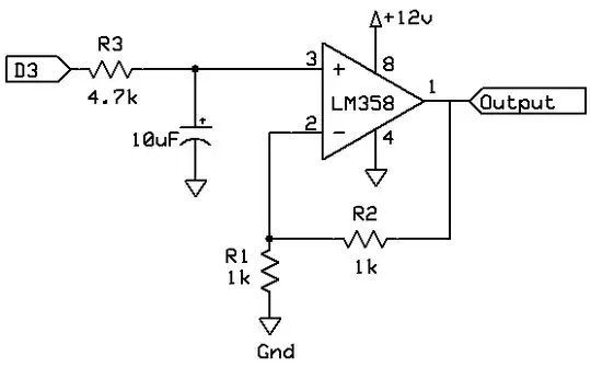
You can take an analog (PWM) output from the Arduino and turn it into 0 to 10 V DC using something like this:
Amplification
The op-amp shown is hooked up as a non-inverting amplifier, where the gain is given by:
VOut / VIn = 1 + (R2 / R1)
Since R2 and R1 in this case are both 1 k then the output will be the input multiplied by:
1 + (1000/1000) = 2
Thus, if we have 5 V coming from D3 we will have 10 V at the output of the op-amp. We need to supply a bit more than 10 V to the op-amp supply pin (pin 8) because this is not a rail-to-rail op-amp, that is, it cannot output all the way up to its supply voltage.
Low-pass filter
The resistor R3 and the 10 µF capacitor form a low-pass filter that filters the PWM signal from the Arduino into a more-or-less smooth DC voltage.
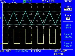
This shows the difference between the Arduino PWM output, and the output of the op-amp:
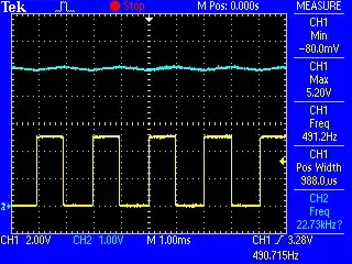
You can see from the scope traces that the yellow line (the PWM output) has a 50% duty cycle, and the blue line (the op-amp output) is 5 V and has a slight ripple.
With a 100% duty cycle, the output is 10 V.
Ripple
Switching the scope to AC coupling we can see how much ripple we have in the op-amp output:
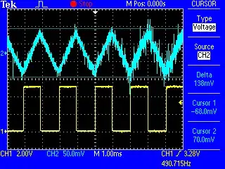
The scale for the blue channel has changed in this image, and the cursor shows that we have around 140 mV of ripple.
We can reduce the ripple by using a larger resistor for R3. For example, making it 10 k reduces the ripple to 86 mV.
The larger resistance make the output less responsive to changes at the input (it takes time to charge or discharge the capacitor) but in testing it still seems pretty responsive.
Code
Test code:
void setup ()
  {
  }

void loop ()
  {
  analogWrite (3, analogRead (A0) / 4);
  }
I had a potentiometer connected to A0 and adjusted it to alter the duty cycle of the PWM output on pin D3.
Theory
You might ask "Why 138 mV of ripple? Why not 50 mV? Why not 200 mV?".
Let's look at the theory. First, the image posted above looks a bit noisy, so let's take an average of the input to the op-amp:
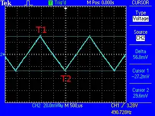
Now we can see that the ripple is about 57 mV (the output of the op-amp would be double that). Indeed, the averaged output is 57 * 2 = 114 mV
The general formula for calculating the time taken by a RC network to reach a certain voltage is:
t = -log((V-Vc)/V)R*C
Where "exp" is the natural exponent.
See Ladyada - RC Delay Calculator.
Also Mathematical treatment of charging and discharging a capacitor.
V  = supply voltage   (initial voltage)
Vc = output voltage   (target voltage)
R  = resistance in ohms
C  = capacitance in farads
t  = time in seconds
These figures will be on the RC discharge graph at roughly the point indicated:

See Wikipedia - RC circuit
Introducing our values for the resistor and capacitor (using Lua) we get:
VS = 5.0       -- supply voltage
VMED = VS / 2  -- 50% duty cycle
VL = VMED - 27.2e-3   -- low voltage as measured
VH = VMED + 29.6e-3   -- high voltage as measured
RES = 4700            -- resistance in ohms
CAP = 10e-6           -- capacitance in farads

T1 = -math.log ( (VS - VH) /VS) * RES * CAP
T2 = -math.log ( (VS - VL) /VS) * RES * CAP

print ("T1 =", T1)
print ("T2 =", T2)
print ("diff = ", T1 - T2, "seconds")
Results:
T1 = 0.0331
T2 = 0.0321
diff =  0.0010 seconds
The time difference is 1 ms which agrees with the observations.