I have a software sending bitmap data to an Arduino Pro 5V 16MHz 328P that drives an LED display (sketch). This works using the USB-Serial adapter for the Arduino Pro with baud rates up to 500000 Baud. Now I wanted to switch to Bluetooth...
I tried connecting a 5V HC-05 module (set to 230400 Baud 8N1) to the hardware RX/TX pins on the Arduino Pro (Pins 0/1) and connect the PC to the Bluetooth serial port wirelessly (e.g. /dev/rfcomm0 on Linux). My problem is that I can receive data on the PC side using a terminal (the 'Ada' string is received), but nothing is displayed on the LED display. I have tried connecting an oscilloscope to the RX/TX pins on the Arduino and Data is arriving from the HC-05 module TX pin to the Arduino RX pin.
When the USB-Serial adapter is connected to the same pins (0/1 instead of the regular pin header) it still works as before, so there should be no connection issues.
What I tried was adding a 5kOhm resistor from the Arduino RX line to ground. (I found this hint somewhere here), but no dice...
I'm not sure what's wrong, because communication IS working over the USB-Serial adapter. Any ideas on what to try?!
4 Answers
A simple 10k/20k voltage divider is enough to bring the 5V arduino logic-level voltage down to ~3.3 for the HC-05. It worked for me anyway.
The default baud rate for HC-05 is 9600 baud. So unless you've changed this with AT- commands you will run into issues. Although I read that some boards default to 38400 - best check your documentation. All the cheap HC-05 boards I've tested default to 9600.
- 773
- 5
- 12
The HC-05 requires a 5V power supply and 3.3V logic. Using SoftwareSerial might be easier for you as you can use pins 8 and 9 rather than 0 and 1, because there can be issues with the USB. Are you transmitting the data you think you are, might Big/Little Endian be an issue? I can get two HC-05 devices to communicate when they are connected to the PC via serial port adapters. However when I replace the receiver with a HC-05 connected to an UNO I get intermittent garbage received. So I suspect there may be some sort of problem with PC->Arduino.
- 5,652
- 1
- 17
- 31
I've run into similar issues with the Arduino and serial communications - it's quite a pain.
There really shouldn't be an issue with your sketch if PC->USB->FTDI->Arduino is working since the same protocols are used (UART is UART, after all).
In regard to the BAUD rate, sure, 230400 should work just fine. For purpose of testing, though, I would slow it down to a measly 9600 or something like that just to rule out any possible issues. (Plus, if I remember right, 9600 or ~11000 is the rate at which it operates when being programmed via AT commands).
Now these are my thoughts on what the problem may be:
You said several times that you have a 5V HC-05 with level shifters. The HC-05 chip itself operates on 3.3V, so typically there is a voltage regulator on the breakout board dropping the voltage down to 3.3V for the Vcc pins and whatever else is pulled high on the chip.
However, I have never seen an HC-05 on Amazon, Sparkfun, or Ebay that actually has a true logic-level shifter on the board itself. Instead (and this is true from my experience with Ebay sellers who claim logic-level shifting built in), there is a voltage divider on the HC-05 RX pin that allows you to send a 5V signal without external resistors. But this isn't bidirectional, so your TX pin still has a logic high level of 3.3V. In short, I think your HC-05 chip really doesn’t have a logic-level shifter.
You may be thinking I’m totally wrong about this, and I very well could be since I don’t have your module in front of me, but just hear me out by reading my reasoning below.
(1) You said you can receive data on your PC. This means the HC-05 is receiving data from a 5V signal and successfully converting it to 3.3V. Great. That works!
(2) You said you were able to get an HC-05 (presumably the same model) to work with an Arduino Due in both directions. The Arduino Due operates on 3.3V, so its logic high threshold is around 2.1v.
(3) On the 5V Arduino Pro, the minimum logic high threshold is (0.6)*Vcc -> 3V. So if the HC-05 is transmitting a signal with a logic high of 3.3V, the Arduino is barely registering it. Factoring in resistance and noise, your signal is probably less than 3.3V. (In fact, my HC-05’s usually push out a signal of ~3V).
Reading that you can see a signal on the HC-05 TX line, but the Arduino is not registering it, I’d bet your signal is below the threshold.
So, I’d fire up your oscilloscope again and check the peak voltage to see what it is.
Additional (Response to "what can I do?)"
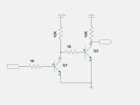
You have a few options. The best option would be to use a bidirectional 3.3V-5V level shifter, but not many people have those laying around. If you happen to have some common components, you could try building a makeshift level shifter like in the images below:
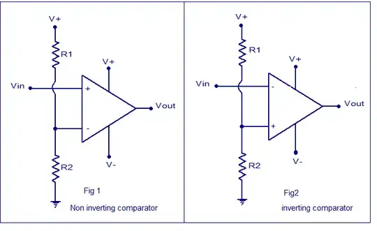
The first "level-shifter" is a a voltage comparator using an opamp. If you go this route, ground V-, tie V+ to 5V, and calculate a voltage divider for around 1.5V. (Note: use the non-inverting setup). A cheap TL272 from Radioshack should work.
The second level shifter uses two NPNs and is self-explanatory.
Note, though, that I haven't tried any of these setups nor know their frequency responses. However, the TL272 should handle signals into the MHzs, and BJTs handle high frequencies rather well. My gut tells me it should work, but just in case, I would use a low BAUD rate.
- 174
- 4
I have used HC-05 modules earlier, with baud rate 9600. But the Chinese modules I recently purchased from eBay appear to be pre-wired for 38400. The module refused to transmit anything, and was receiving garbage on the Rx side. So I changed the line
softSerial.begin (9800);
to
softSerial.begin (38400);
This solved my problem.
- 141
- 6