4

I'm trying to power a Raspberry Pi 4 via a 6-AA battery pack via buck converter which steps it down to 5V but it gets stuck in a reboot loop on boot up.

Watching the display on the buck converter, the voltage dips below 4.6V and the red light goes off on the RPI and it reboots again (I only get as far as seeing the rainbow screen and then the 4 raspberries).

I've gone up to 5.3V on the converter but it still dips down too low. I got it to boot fully once on rechargeable batteries and once on alkaline but after that no luck. Once when watching on alkaline it seemed like it didn't dip that time for some reason and then right after when trying it again it did dip. A wall power supply works fine.

What's the best way to solve this? Add a component of some sort or by some other method? Perhaps increasing the voltage above 5.3V if that's safe to do?

The 5V output of the buck converter is going to GPIO pins 2 and 6. In case it matters, the buck converter I'm using is Amazon item B00Q48BRFO.

====UPDATE Oct-14-2020====

Thanks to the helpful answers. The last things I'd like to know are:

  1. Any there concerns about damaging something by starting the Pi up with the USB power supply and then unplugging it and letting it continue running on the battery pack but at lower power draw since under my intended usage? I.e. is it safe to switch out power like that? I'd have the battery pack -> converter already plugged into the 5v and ground pins on the GPIO and then just pull out the USB power. I understand the Pi may not run for long on batteries given its draw, but that's okay.
  2. Instead of getting a different converter like Dmitry mentioned may help, is there a capacitor or something (not too knowledgeable on electronics components) that I could stick somewhere to provide for the peak draw on boot up? Since it has worked a couple of times as is, I'm assuming I have just barely not enough to handle, so was hoping this could be an option.
g491
  • 143
  • 1
  • 5

4 Answers4

6

You've not explained or shown how you have your batteries arranged, nor provided any specs on them. But it seems likely they are in series - thereby providing ~ 9V output.

Batteries in series can provide no more current that a single battery, and even a good quality AA cell isn't capable of much more than 1 amp. And so your battery pack will be unable to source more that 1 amp to the converter - that's not likely to be sufficient as the calculations below will show.

It's not possible to do a calculation with much accuracy because there are several variables missing - the battery specs and the regulator efficiency being two important ones. However, we can make assumptions as we step through the calculations:

1. All of the Power comes from your batteries: P = V x I

For a series arrangement of 6 AA cells, we get ~ 9 VDC The current capacity in a series arrangement of batteries however is no more than that of a single battery. Also, placing batteries in series means that the effective internal resistance of the series arrangement is 6X that for a single battery. Some estimates state the internal resistance of a AA cell will be at best 0.15, so about 0.9 total for 6 in a series arrangement. Also - this single battery resistance increases as the battery discharges - perhaps to 0.75 at 90% discharge - or 4.5 total for 6 batteries in a series arrangement.

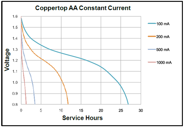
I found this graphic depicting how much current a good AA battery can source:

enter image description here

As can be seen from inspection, voltage goes downhill rapidly at any discharge rate needed to sustain an RPi. And while Duracell's graphic shows that 1 Amp may be sourced, this will be be for only a very short period of time, and with a fresh, new battery. Let's choose 500 mA as a practical limit for the maximum current the batteries may source, and use that figure to calculate the power that the batteries can source:

Pbatt = V x I = 9V x 0.5A = 4.5 Watts

2. Losses are incurred before the power reaches the RPi:

The calculations show the batteries are optimistically capable of supplying 4.5 Watts. However, some of this power will be lost due to the internal resistance of the battery, and the inefficiency of the the buck regulator (any regulator actually). These losses must be subtracted from the power delivered by the batteries. We'll estimate these losses as follows:

Rinternal = 0.3 (for one battery; 1.8 for 6 in series)

Efficiency of buck regulator = 75%

Power lost in internal resistance: PR = I2 x Rinternal

PR = (0.5A)2 x (6 x 0.3) = 0.45 Watts

Converter efficiency loss = Pin x ( 1 - Efficiency )

Conversion loss = (4.5 W - 0.45 W) x ( 1 - 0.75) = 1.0 Watts

3. Power delivered to RPi: Pbatt - PR - Conversion loss = 3.0 Watts

Again - the battery discharge curves above inform us this will decrease rapidly over time; the situation is exacerbated by the fact that during startup/boot the RPi will draw more power than it will in a quiescent, idle state. Measurements on my RPi 4B show that it will draw approx 2.5W in an idle state, but the "official documentation" places that figure at 3.0W (600mA). Given that the low voltage threshold is 4.63V, you won't get much run time out of 6 new AA cells.

Recommendations

The "best way" to solve this is to forget about trying to power an RPi from a bunch of AA batteries. Instead, get a rechargeable Li-Ion battery pack. Some are called "portable chargers" or power banks", and supply 5V at their USB output. This eliminates the need for a separate regulator, and the internal batteries can be recharged many times. The other option is a DIY approach - as you've planned, except using a Li-Ion pack instead of AA cells.

However, if you have reasons for pursuing this particular approach with the AA batteries that you don't wish to disclose, and you don't mind laying out more cash for a good quality regulator you could consider a boost or a buck-boost converter. These converters have the advantage of allowing you to put your batteries in a parallel arrangement. Some of them are also more efficient than the buck converter. This table provides a fairly comprehensive overview of the characteristics of the various topologies. You want a topology that has a Yes in the right-most column ( Vout > Vin ). But you should keep your expectations very low - the cost will certainly be higher, but the performance advantage over your current setup will be slight.

Seamus
  • 23,558
  • 5
  • 42
  • 83
2

From experience I bet the problem is a not-powerful-enough converter (I remember a question asked earlier, where an even smaller converter was put to test and failed miserably, killing the Pi in the process). Look for a converter featuring a ring inductor with thick copper wire around it: those can typically handle enough current to start a Pi.

Increasing the voltage of your converter will not increase the current it can deliver. The absolute maximum rating of the Pi power converter is 5.45V, and a cheap converter set to steady 5.3V can easily deliver a spike above 5.5V for a short moment during startup, so increasing the voltage further increases the risk of destroying the Pi.

Fresh AA batteries can deliver 1.5-2A @ 1 volt, so 6 of them there should deliver about 9-12W: enough power to start a Pi 4 without any external peripherals. They won't last longer than half an hour with such a load though, and even a single half-discharged cell may kill the power output of the whole bank. If you want to actually use a Pi with batteries, you will need a better power source.

Answers to additional questions:

  1. Switching between two power supplies has an inherent problem: at some point you will need both power supplies connected, which could let very large currents flow from one supply into the other. Some power supplies can survive this for a few seconds, others won't.

  2. Yes, you can use capacitors to smooth power peaks, however, for peaks which last for ~10-30 seconds, the capacitor will have to be very large, and its poor efficiency (you can recover less than 50% of power from a capacitor in a linear active circuit) will become a limit too. To give you an idea of the capacitance value, this question suggests that 12.5 Farad is enough to keep a Pi 3 powered for about 10 seconds from the capacitor alone.

Dmitry Grigoryev
  • 28,277
  • 6
  • 54
  • 147
2

I had exactly the same issues as you describe here. I was also following instructions from the book Learn Robotics with Raspberry PI. For my project, I was using pi 3 model b+. I solved the problem by replacing the battery holder with another one of better quality. If it helps, this is the battery holder I used https://www.ebay.co.uk/itm/133616385476

Naima
  • 21
  • 1
0

Based on previous answers it looks like you have a lower-power-offer-than-necessary kind of problem. As mentioned by someone, when you have cells in series the total output current is as high as the one for one single cell, that might be your problem right there. Also keep in mind that batteries discharge and their voltages drop, so there may be a point where there is not enough voltage for your buck to work. My recommendation would be to put cells in paralell and also add one or more cells in series as well to increase the voltage.